The welded pipe manufacturing process systematically transforms flat steel into a durable cylindrical product. A precise weld is a critical step in this manufacturing process. This precision ensures each welded pipe meets strict standards for strength and integrity. Many essential industries rely on these pipes for their operations.
- Energy Sector: For oil, gas, and water pipelines.
- Construction: In structural components like beams and columns.
- Automotive Manufacturing: For exhaust systems and vehicle frames.
The global market reflects this widespread use and projected growth.
| Metric | Value |
|---|---|
| Market Size (2023) | USD 50 billion |
| Projected Market Size (2032) | USD 70 billion |
| CAGR (Forecast Period) | 3.8% |
Stage 1: Raw Material Preparation in the Welded Pipe Manufacturing Process
The journey to create high-quality welded pipes begins with careful preparation of the raw material. This foundational stage ensures the steel is ready for forming and welding, setting the standard for the final product’s integrity and performance. Every step, from selection to joining, is executed with precision.
Steel Coil Selection and Inspection
Manufacturers first select the appropriate steel grade based on the pipe’s intended application. Each grade offers distinct properties for strength, corrosion resistance, and temperature tolerance. Inspectors then verify the raw material for any defects. The choice depends on the pipe’s final use:
- Carbon Steel (e.g., S355, API 5L X52): This is the most common and economical choice. It is reliable for general construction, water lines, and oil and gas transport.
- Low-Alloy Steel (e.g., S460, A572 Gr.50): This steel provides higher strength and toughness. It is ideal for demanding projects like offshore structures and bridges.
- Stainless / High-Alloy Steel (e.g., 304, 316): This grade offers excellent corrosion resistance. It is essential for chemical plants and process piping systems.
Uncoiling and Flattening the Steel
Once selected, the large steel coil is loaded onto an uncoiler. This machine carefully unwinds the steel strip. A powerful flattener or leveler then removes the coil’s natural curve, transforming it into a perfectly flat sheet. This step is critical for achieving uniform pipe dimensions. These machines handle impressive specifications:
| Component/Feature | Specification/Function |
|---|---|
| Uncoiler Capacity | Handles coils up to 40 tons |
| Material Thickness | 4mm – 25mm (0.16″ – 1.0″) |
| Hydraulic Support | Assists in loading and guiding heavy coils |
| Flatness Control | Integrated levelers ensure a uniform surface |
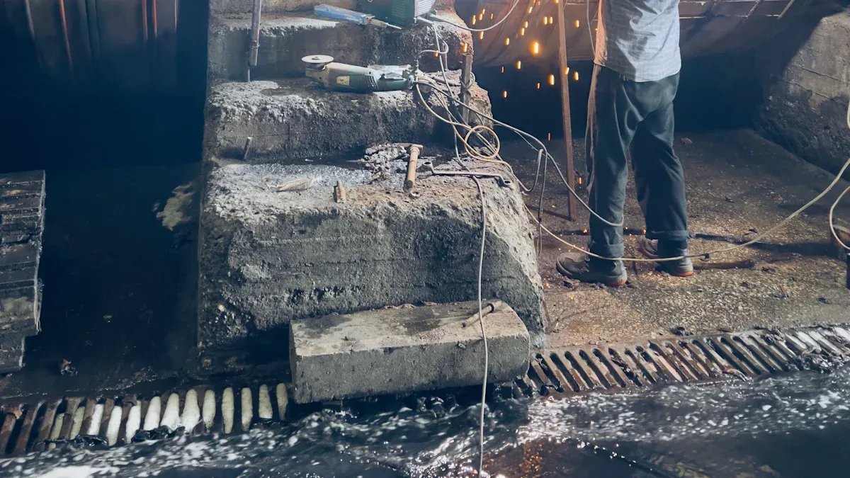
End Shearing and Joining
Tip: To maintain a continuous production flow, the end of one coil must be joined to the start of the next. This prevents costly downtime.
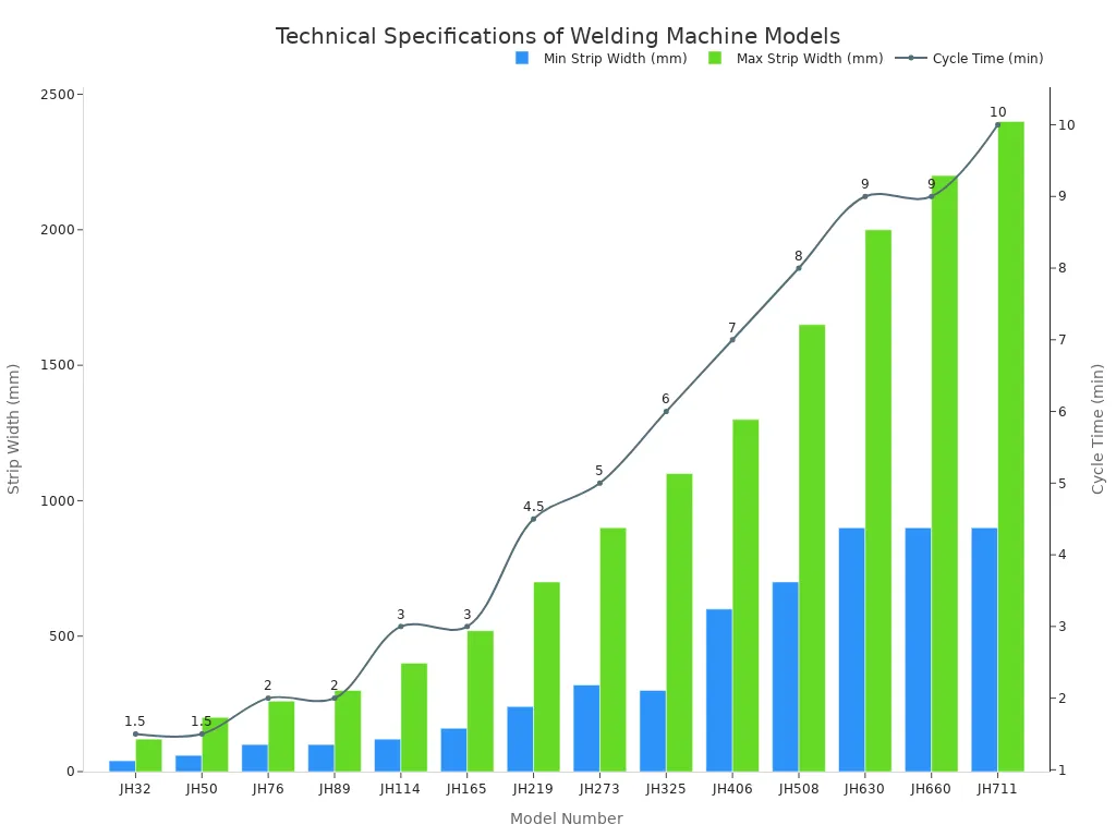
A shear and end welder automates this task. First, hydraulic blades shear off the irregular ends of two separate steel strips. The machine then perfectly aligns the clean edges and butt-welds them together using a method like MIG welding. This creates a strong, seamless transition, allowing the manufacturing process to continue without interruption. The cycle time varies based on the machine model and steel dimensions, as shown below:
Stage 2: Forming the Tube for Welded Pipes
After preparing the raw material, the flat steel strip enters the forming stage. This crucial step shapes the steel into a cylindrical form, preparing it for welding. The precision here directly impacts the final dimensions and quality of the welded pipe.
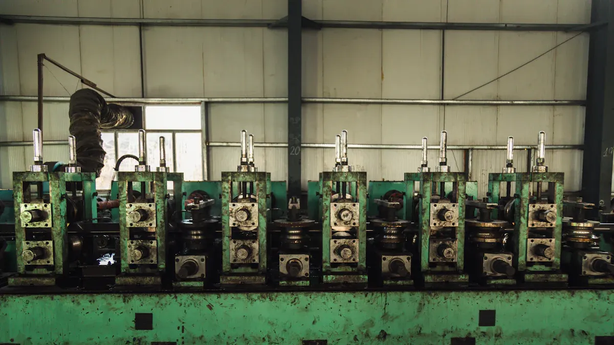
The Role of Forming Rollers
The heart of the forming process is a series of powerful rollers. These rollers are arranged in a long line called a forming mill. Each set of rollers, or “stand,” progressively bends the steel strip a little more. This gradual approach prevents stress and ensures a uniform curve along the entire length of the strip. The rollers apply controlled pressure from different angles, slowly curling the flat edges upward.
Creating the Open-Seam Tube
As the steel strip moves through the forming mill, its flat shape transforms. The edges curl inward until they almost touch, creating a cylinder with a narrow gap. This product is known as an “open-seam tube.” The gap, or seam, is perfectly aligned for the next stage: welding. The quality of this open-seam tube is critical. A consistent gap ensures a strong and reliable weld, which is essential for high-quality welded pipes.
Common Forming Methods
Manufacturers primarily use two methods to form the tube: traditional roll forming and cage forming. Each method has distinct advantages depending on the production needs. Roll forming uses dedicated rollers for each pipe size, while cage forming uses adjustable rollers for faster changeovers. The choice of method affects efficiency, surface quality, and the types of pipes that can be produced.
| Feature/Aspect | Roll Forming | Cage Forming |
|---|---|---|
| Mechanism | Gradual bending through a series of dedicated roll stands. | Bending occurs via multiple rows of small, passive rollers. |
| Roller Type | Dedicated roller sets are required for each pipe size. | Uses adjustable small rollers housed in a “cage” section. |
| Surface Quality | Provides smoother surfaces due to distributed deformation. | Reduces scratches because small rollers minimize speed differences. |
| Size Changes | Requires time-consuming roll replacement for new sizes. | Allows for faster changeovers, which boosts efficiency. |
| Best For | A broad range of pipes, including thick-walled steel. | Thin-walled pipes; less suitable for high-strength steel. |
Stage 3: The Welding Manufacturing Process
Once the steel is formed into an open-seam tube, the welding manufacturing process begins. This stage permanently joins the edges to create a sealed pipe. Different welding techniques are used depending on the pipe’s intended application and required strength. Each method ensures a strong, reliable seam.
Electric Resistance Welding (ERW)
Electric Resistance Welding (ERW) is a common method for creating a longitudinal weld. The process passes a high-frequency electric current through the edges of the open-seam tube. This current heats the steel to a forging temperature. High-pressure rollers then press the hot edges together, forming a strong bond without using any filler material. Modern ERW offers several key benefits:
- High Efficiency: Continuous production leads to lower costs.
- Precise Dimensions: The cold-forming process ensures uniform pipe size and a smooth surface.
- Strong Welds: The final weld is often as strong as the parent steel.
The welding speed in this process depends on the pipe’s wall thickness. Thicker steel requires more heating time, which slows down the production line.
| Steel Pipe Thickness (mm) | Welding Speed (m/min) |
|---|---|
| 2–3 | 40 |
| 4–6 | 25 |
| 6–8 | 12 |
| 10–16 | Below 12 |
Note: Controlling the input power is critical. Too little power results in a weak weld, while too much power can cause defects like splashes or pinholes.
High-Frequency Induction (HFI) Welding
High-frequency welding is an advanced form of ERW. It uses an induction coil to generate the electric current without direct contact. This method provides excellent control over the heating process. As a result, high-frequency welding is preferred for many applications, including:
- Water and gas distribution lines
- Low-pressure fluid systems in industrial plants
- Onshore oil and gas pipelines
- Structural components for buildings and towers
Submerged Arc Welding (SAW)
For pipes with very thick walls, manufacturers use submerged arc welding (SAW). This is one of the most robust welding processes available. During submerged arc welding, a machine feeds a consumable electrode wire to the seam. A layer of granular flux covers the welding area, protecting the molten metal from the air. This creates a clean, strong, and uniform weld. The flux melts to form a protective slag layer, which is removed after the weld cools. Submerged arc welding is ideal for large-diameter pipes used in high-pressure and structurally demanding environments.
Laser Beam Welding (LBW)
Laser Beam Welding (LBW) represents one of the most advanced welding techniques available for pipe manufacturing. This process uses a highly concentrated laser beam as a heat source. The laser melts and fuses the edges of the open-seam tube with exceptional precision. This method creates a deep and narrow weld, minimizing the heat-affected zone around the seam. A shielding gas, such as argon or helium, often protects the molten metal from atmospheric contamination.
The focused energy of the laser provides several distinct advantages. Manufacturers choose LBW for applications demanding superior quality and speed.
- High Welding Speed: Lasers can weld much faster than many conventional methods.
- Minimal Distortion: The low heat input reduces thermal stress and warping in the pipe.
- Excellent Weld Quality: The process produces a clean, strong, and smooth weld with a fine grain structure.
- Versatility: It works well with a wide range of materials, including high-strength and stainless steels.
These characteristics make LBW one of the premier welding techniques for high-value products. The table below compares key aspects of LBW with traditional ERW.
| Feature | Laser Beam Welding (LBW) | Electric Resistance Welding (ERW) |
|---|---|---|
| Heat Input | Very Low and Concentrated | High and Less Focused |
| Welding Speed | Up to 100 m/min | Typically 12–40 m/min |
| Weld Width | Narrow (e.g., 1–2 mm) | Wider (e.g., 4–6 mm) |
| Post-Weld Finish | Minimal cleaning required | Often requires scarfing/grinding |
Application Highlight: The automotive industry frequently uses LBW to produce stainless steel exhaust pipes. The process delivers the clean appearance and corrosion resistance needed for modern vehicles. It is also ideal for manufacturing high-purity tubes for the food and pharmaceutical sectors.
Stage 4: Sizing, Finishing, and Coating
After welding, the pipe is not yet complete. It enters the finishing stage, where it is treated, sized, and cut to meet exact specifications. These steps ensure the final product has the required mechanical properties and dimensional accuracy for its intended application.
Post-Weld Heat Treatment (Normalizing)
The intense heat from welding creates stress within the steel. Post-Weld Heat Treatment (PWHT) is a critical process that relieves this stress. Normalizing is a common PWHT method where the pipe is heated and then air-cooled. This process refines the grain structure of the steel around the weld. The primary goals of this treatment are to:
- Reduce residual stresses to prevent cracking.
- Improve the pipe’s toughness and ductility.
- Minimize the risk of stress corrosion cracking.
- Ensure the pipe remains dimensionally stable during its service life.
Normalizing typically requires heating the steel to a temperature between 810°C and 930°C (1490°F and 1706°F). This controlled heating and cooling cycle makes the material more uniform and durable.
Sizing and Shaping the Pipe
The pipe next moves through a sizing mill. This machine uses a series of rollers to fine-tune the pipe’s diameter and roundness. The process ensures the pipe meets strict industry standards, such as those from the American Petroleum Institute (API). A precise final shape is essential for a perfect fit in pipelines and structural assemblies. The quality of the initial weld directly impacts how easily the pipe can be sized to these tight tolerances.
Wall Thickness t mm (in) | Tolerance mm (in) (Welded Pipe) |
|---|---|
| ≤ 5.0 (0.197) | ± 0.5 (0.020) |
| > 5.0 (0.197) to < 15.0 (0.591) | ± 0.1 t |
| ≥ 15.0 (0.591) | ± 1.5 (0.060) |
Straightening and Cutting to Length
Pipes can develop slight bends during manufacturing and cooling. A straightening machine corrects these imperfections. The most common method is mechanical straightening, where rollers apply pressure to bend the pipe back into a perfectly straight line. This step is vital for applications where alignment is critical, such as in pipelines or building frames. After straightening, an automated saw cuts the continuous pipe into standard or custom lengths. This final cut prepares the pipe for end finishing and shipment, ensuring it is ready for immediate use upon delivery. The integrity of the original weld is maintained throughout this process.
End Finishing and Beveling
After cutting, manufacturers prepare the pipe ends for connection. This step, known as end finishing, is essential for field installation. The most common finishing method is beveling. A machine cuts a precise angle on the edge of the pipe wall. This creates a V-shaped groove when two pipes are placed together, which allows for a deep and strong weld.
The angle of the bevel depends on the pipe’s wall thickness and the welding standards for the project. Certain angles are standard across the industry to ensure compatibility and weld quality.
- The American Petroleum Institute (API) 5L standard often requires a bevel angle of 30° (with a tolerance of ±5°).
- A 37.5° angle is another common choice, especially for welding that follows ASME codes.
- Most beveling angles fall between 30° and 45° to create the ideal groove for welding.
Applying Protective Coatings
Steel pipes are vulnerable to corrosion from moisture, chemicals, and soil. Manufacturers apply protective coatings to extend the pipe’s service life. The choice of coating depends on the pipe’s final environment and application. A proper coating acts as a durable barrier against rust and damage.
Key Insight: Selecting the right coating is crucial. A pipe used underground needs different protection than one exposed to chemicals in a factory.
Several types of coatings offer distinct advantages. Each one provides a specific kind of protection.
- Fusion-Bonded Epoxy (FBE): This powder coating melts and fuses to the steel, creating an extremely tough barrier against corrosion.
- Polyethylene (PE): A plastic-based coating that offers excellent protection from moisture, making it ideal for buried pipelines.
- Zinc (Galvanizing): This coating sacrifices itself to protect the steel underneath. It is a cost-effective and reliable method for preventing rust.
- Epoxy: Liquid epoxy coatings provide great resistance to chemicals and can create a smooth interior surface that improves fluid flow.
This final layer of defense ensures the welded pipe performs reliably for years.
Stage 5: Quality Control in the Manufacturing Process of Welded Pipes
Quality control is the final and most critical stage in the manufacturing process of welded pipes. Inspectors perform a series of rigorous tests to verify that every pipe meets industry standards for safety and performance. This comprehensive testing ensures the integrity of the final product.
Visual and Dimensional Inspection
The first step in quality control is a thorough visual and dimensional inspection. Inspectors carefully examine each pipe for any surface flaws and measure its dimensions to ensure accuracy. This hands-on check confirms the quality of the manufacturing process. Key criteria include:
- Dimensional Inspection: Inspectors use tools like calipers to measure the weld’s size and length.
- Weld Reinforcement: They check that the weld bead height meets project requirements.
- Weld Profile: They assess the weld for a consistent shape and look for issues like undercuts.
- Weld Bead Appearance: They evaluate the surface for smoothness and uniformity.
- Visual Examination: Inspectors look for obvious defects like cracks or porosity.
Hydrostatic Testing
Hydrostatic testing checks for leaks and confirms the strength of the welded pipes. Technicians fill the pipe with water and pressurize it to a level significantly higher than its normal operating pressure. They hold this pressure for a set duration to see if the pipe can withstand the force without leaking or bursting.
According to the American Society of Mechanical Engineers (ASME) B31.3 standard, the test pressure must be at least 1.5 times the design pressure. Inspectors maintain this pressure for a minimum of 10 minutes to check for any leaks.
Ultrasonic Testing (UT)
Ultrasonic Testing (UT) is a non-destructive method used to find internal flaws. An inspector uses a special tool called a transducer to send high-frequency sound waves into the pipe’s weld seam. These sound waves travel through the steel and reflect off any hidden defects. The transducer records these reflections, allowing inspectors to identify the flaw’s location and size without damaging the pipe. This advanced step in the manufacturing process can detect several types of internal imperfections, including:
- Cracks
- Voids
- Inclusions
- Other structural irregularities
Radiographic (X-Ray) Inspection
Inspectors use Radiographic Testing (RT), or X-ray inspection, to see inside a weld. This method creates an image of the weld’s internal structure on film. It reveals hidden flaws like porosity or cracks that are not visible on the surface. This test is essential for ensuring the integrity of high-pressure welded pipes. Industry codes, such as ASME B31.3 and AWS D1.1, often require this inspection.
Specific standards dictate when X-ray inspection is necessary. For example, the ASME code requires:
- Testing 5% of butt welds for pipes in Category D Fluid Service (non-toxic fluids).
- Testing 20% of butt welds for pipes in Category M Fluid Service (highly toxic fluids).
- Routine testing to confirm a welder’s capability.
Magnetic Particle Inspection (MPI)
Magnetic Particle Inspection (MPI) is a fast and effective method for finding surface and near-surface defects in ferromagnetic materials. An inspector first magnetizes the pipe. Then, they apply fine iron particles to the surface. Any crack or flaw will disrupt the magnetic field, causing the particles to gather at that spot. This makes even tiny defects easy to see. MPI offers several key advantages:
- High Sensitivity: It detects very small cracks and discontinuities.
- Speed and Efficiency: The process is quick and provides immediate results.
- Cost-Effectiveness: It is a lower-cost method compared to other non-destructive tests.
- Portability: Inspectors can use portable equipment to perform tests on-site.
Final Marking and Bundling
The last step in the manufacturing process of welded pipes is marking and bundling. Each pipe receives permanent markings with critical information. This ensures full traceability from the factory to the field. The markings typically include the manufacturer’s name, pipe dimensions, material grade, and the standard it meets (e.g., ASTM A53). A unique heat number links the pipe back to its original production batch. After inspection and marking, machines bundle the pipes together with steel straps. This prepares them for safe and efficient transport to the customer.
The journey from a flat steel coil to a finished product is defined by five key stages. This systematic manufacturing process includes raw material preparation, forming, welding, finishing, and comprehensive testing. This method ensures every welded pipe is produced to precise specifications, guaranteeing reliability and performance. Understanding these steps demystifies the engineering behind this essential industrial component. Modern advancements like robotics and AI continue to refine the manufacturing process, creating stronger and more sustainable welded pipes for the future. This highlights the quality control required to create a dependable welded pipe.
FAQ
What is the main difference between ERW and SAW pipes?
Electric Resistance Welding (ERW) uses high-frequency current and pressure to forge a seam without filler metal. Submerged Arc Welding (SAW) melts a consumable wire electrode under a flux layer to join thicker steel walls. SAW is ideal for high-pressure, large-diameter pipes.
Why is post-weld heat treatment important?
The welding process creates internal stress in the steel. Manufacturers perform heat treatment, like normalizing, to relieve this stress. This step improves the pipe’s toughness and ductility, preventing potential cracks and ensuring the material is strong and stable for its final application.
What does hydrostatic testing prove?
Hydrostatic testing confirms a pipe’s strength and leak-proof integrity. Technicians fill the pipe with water and apply high pressure, typically 1.5 times its design pressure. This test proves the weld and pipe body can safely handle intense forces without failing or leaking.
How do manufacturers ensure pipe straightness?
Pipes can bend slightly during manufacturing. A straightening machine uses a series of rollers to apply precise pressure, correcting any curves. This process ensures the pipe meets strict alignment standards required for pipelines and structural projects, guaranteeing a perfect fit during installation.