NEWS

Structural Design Analysis of High‑End Shock Absorber Guide Assemblies with Oil Reservoirs and Bypass Filtration Screens

Abstract This article introduces the pressure‑difference compensation principle of the auxiliary oil reservoir, the online self‑filtration function of the bypass screen, and the application of the 7075 aluminum alloy CNC‑machined housing. Structural Diagram Figure 3: Schematic diagram of the shock absorber guide assembly (oil seal seat) structure (including guide bearing, oil seal, dust cover, and oil scraper ring) Core Technical Points Detailed Content In shock absorbers used in racing cars, off‑road modified vehicles, and certain top‑tier luxury passenger cars, the guide assembly has evolved into a highly integrated, intelligent fluid management module.

view detail

Collaborative Optimization Design of Sealing and Guidance for Shock Absorber Piston Rod Guide Bushings

Abstract This article discusses the design principles of floating elastic guide bushings, three types of lip seal structures, and the oil scraper ring lubrication system. Structural Diagram Figure 3: Schematic diagram of the shock absorber guide assembly (oil seal seat) structure (including guide bearing, oil seal, dust cover, and oil scraper ring) Core Technical Points Detailed Content During actual operation of a shock absorber, the guide assembly must not only withstand axial alternating loads but also cope with complex multi‑directional lateral forces generated by wheel movement.

view detail

Collaborative Matching Design of the Base Valve and Floating Piston in Modern Passenger Car Shock Absorbers

Abstract This article explains the working principle and matching design requirements of the base valve and floating piston in monotube shock absorbers. Structural Diagram Figure 2: Schematic diagram of the base valve (compensation valve) structure in a shock absorber (including strainer/filter screen, valve seat, valve disc, and return spring) Core Technical Points Detailed Content In a monotube high‑pressure shock absorber, the function of the base valve is fundamentally different from that in a twin‑tube shock absorber.

view detail

System Matching and Comprehensive Performance Analysis of Core Components for Automotive Hydraulic Shock Absorbers

Abstract From the perspective of system matching, this paper analyzes the coordination relationship among pistons, base valves and guides of hydraulic shock absorbers, summarizes common failure modes of key components, and prospects the future technical development trends. Core Knowledge Points Detailed Content The performance of automotive hydraulic shock absorbers is not simply a combination of individual parts. It requires in-depth system matching of core components including piston valve assemblies, base valves, guides, cylinders and piston rods in terms of fluid mechanics, structural mechanics and tribology. System Matching Logic All core components work interactively during operation. Any adjustment to the structure, size or material of one part will affect the operating state of the whole shock absorber. Therefore, it is necessary to adopt overall tolerance chain design and multi-physics field simulation to ensure coordinated performance of all parts. Division of Work for Three Core Components Each component undertakes distinct core functions. The piston valve system controls the overall damping stiffness. The base valve regulates the smoothness and compliance during compression strokes. The guide directly influences the product service life and defines the basic level of vehicle NVH performance. Manufacturing Process Requirements Advanced fully automatic oil filling and rolling technology is adopted in production. It keeps the assembly clearance strictly within 0.02 mm, effectively removing surface burrs and eliminating internal residual stress, so as to guarantee stable long-term operation. Failure Mode Analysis Statistically, 60% of early failures of shock absorbers occur on guide seals and valve plates due to fatigue damage. The fundamental causes are unreasonable compensation performance of base valves and insufficient internal cleanliness of the shock absorber. Future Technical Trends The industry will continuously explore and apply new technologies. Magnetorheological damping, lightweight structural materials, built-in intelligent sensors and digital twin systems will be widely used to realize closed-loop design, testing

view detail

Structural Design and Friction & Wear Mechanism Analysis of Shock Absorber Guide (Oil Seal Housing)

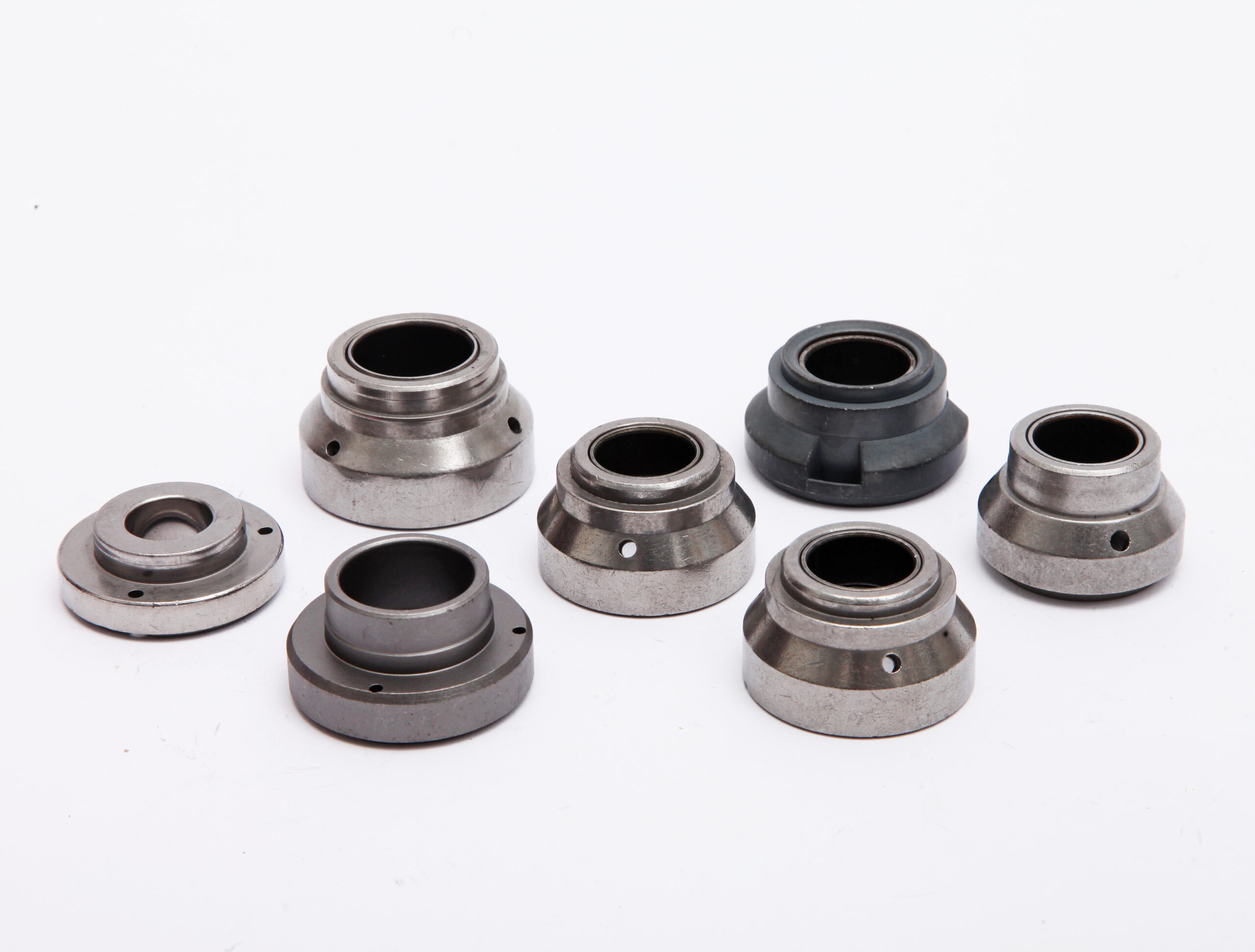
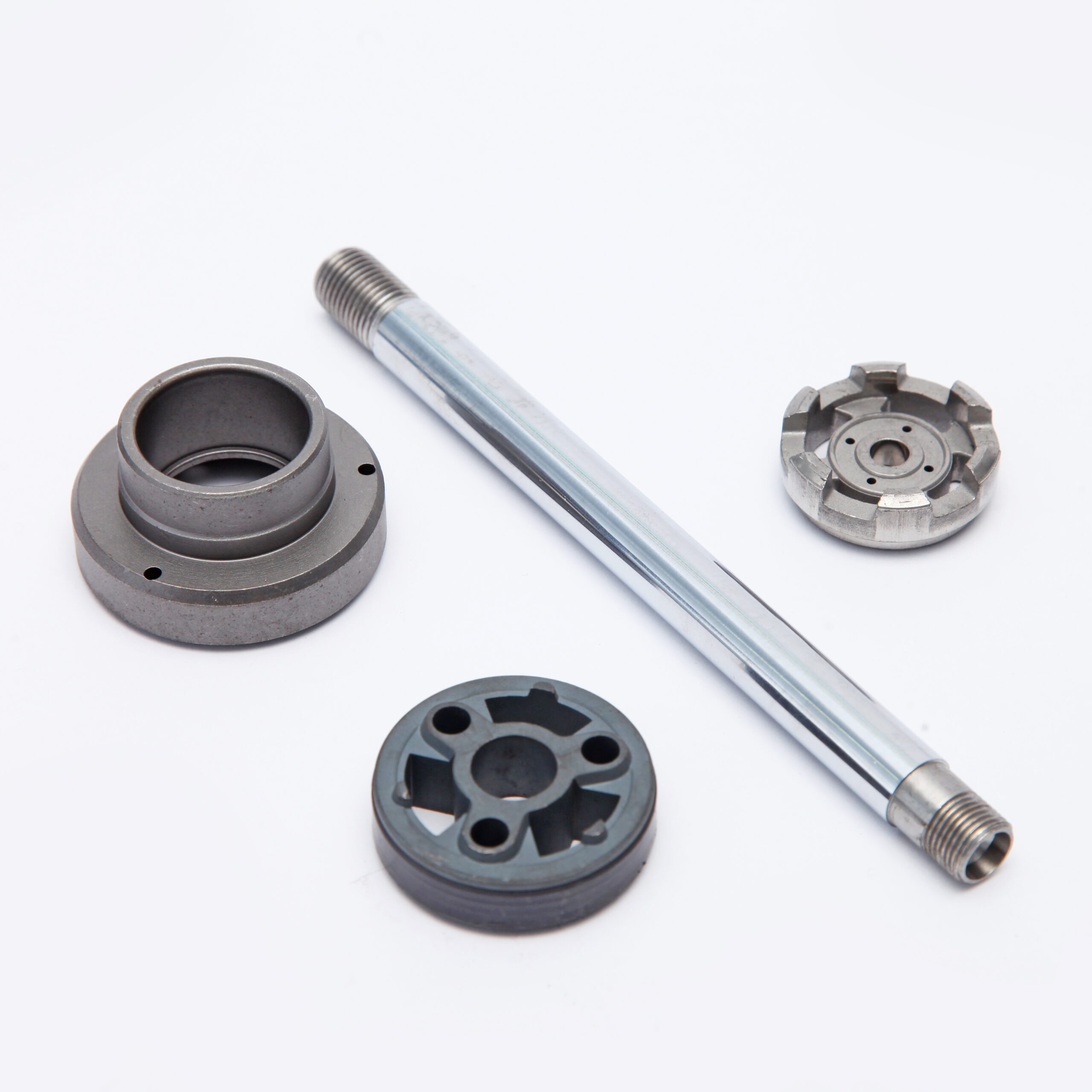
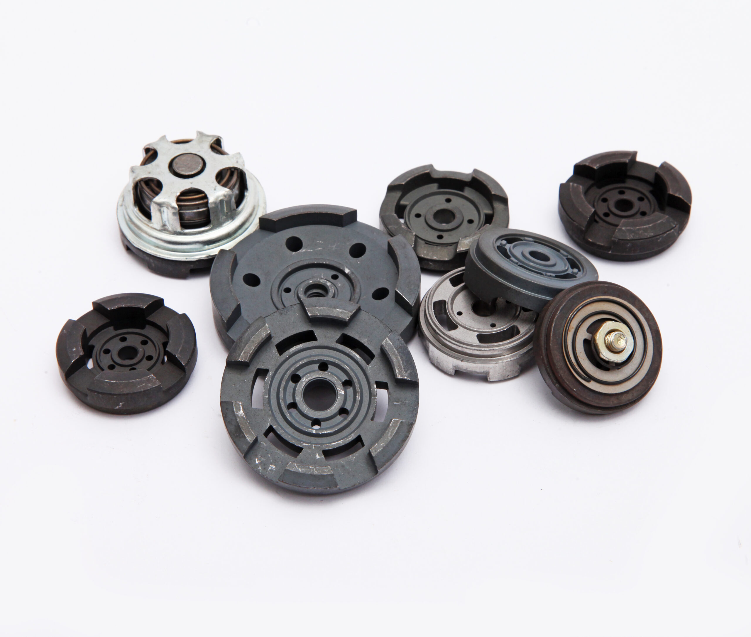
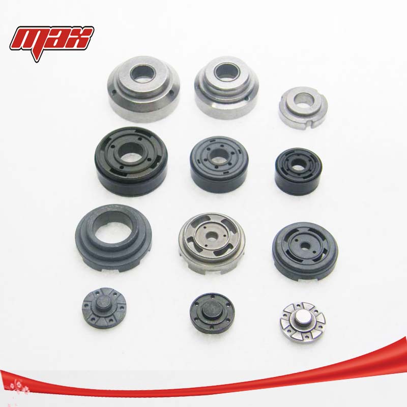
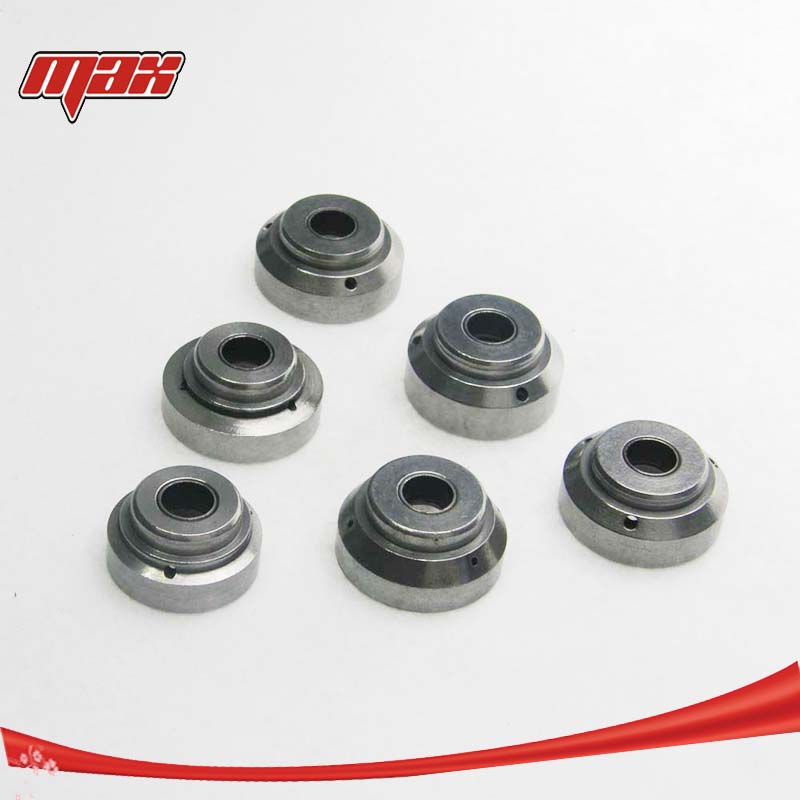
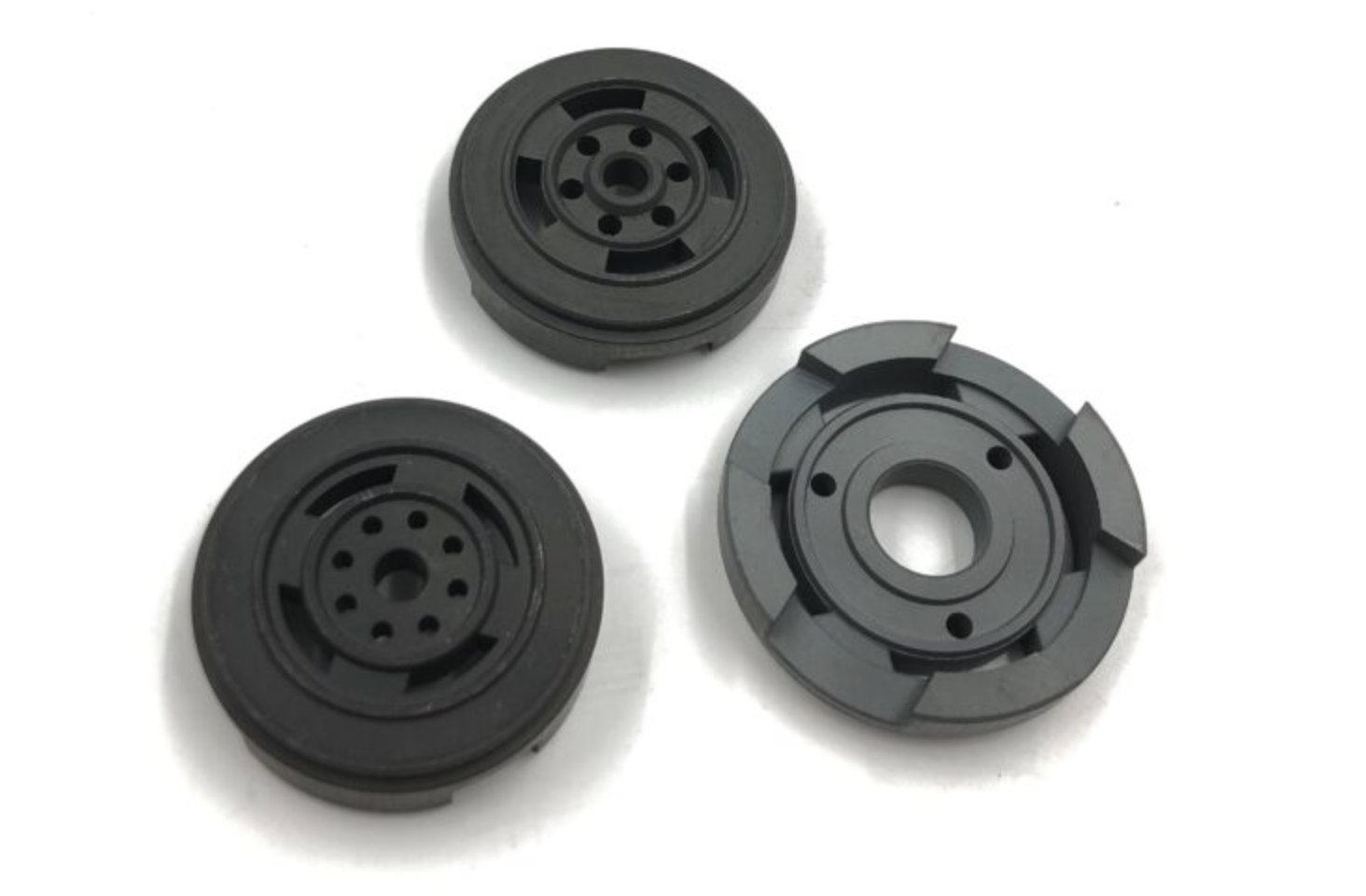
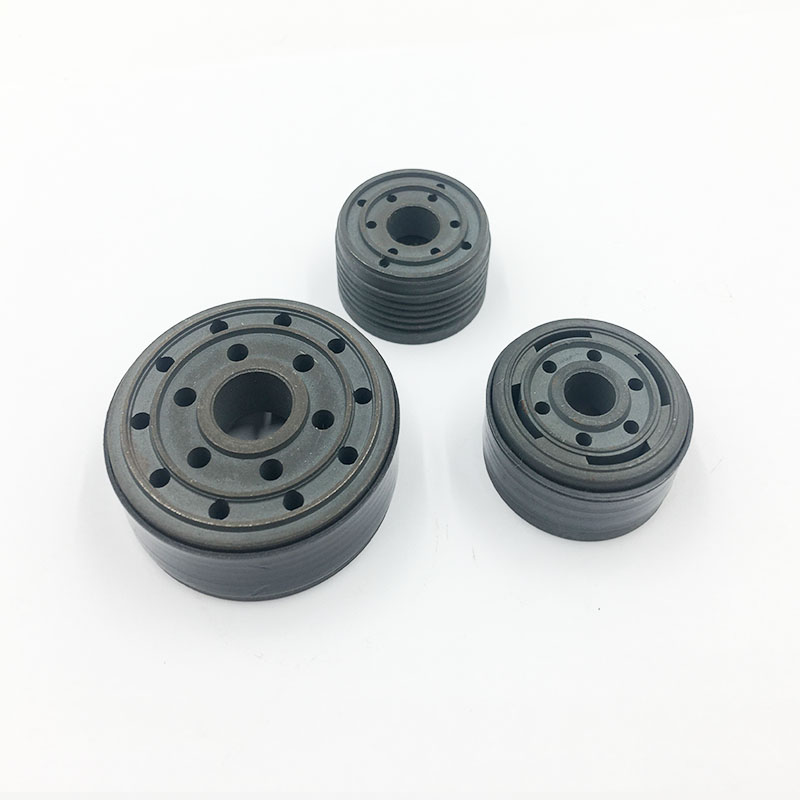
Abstract This paper analyzes three core functions of the guide. It compares the advantages and disadvantages of split-type and integrated structures, and explores the characteristics of different materials for guide bearings. Meanwhile, it studies the generation mechanism of friction and wear, and verifies the optimal material matching scheme. The research indicates that the machining and assembly accuracy of the guide directly affects the NVH performance and full-life reliability of shock absorbers. Structure Diagram Core Knowledge Points Detailed Content The guide, also commonly known as oil seal housing or piston rod guide housing, is a core positioning component installed at the top of the working cylinder of shock absorbers. Three Core Functions of the Guide First of all, it provides accurate radial guidance for the reciprocating piston rod, restricting radial deflection and ensuring smooth linear movement. Secondly, it acts as a dedicated mounting base for oil seals and dust seals, keeping sealing components in correct position and maintaining reliable sealing performance. Thirdly, it bears continuous lateral forces transmitted from wheels during vehicle driving, steering and crossing bumpy roads, so as to protect the piston rod and internal parts from eccentric load damage. Split-type VS Integrated Structure Split-type Structure This structure consists of several separate parts assembled together. It allows flexible production and easy assembly, and worn parts can be replaced individually for lower maintenance costs. However, multiple fitting surfaces will lead to accumulated clearance errors, resulting in poor concentricity during operation. It will further cause eccentric wear of oil seals and eventually lead to oil leakage. Integrated Structure The integrated injection-molded guide housing integrates all functional structures into one piece. It features high overall rigidity and excellent concentricity, effectively reducing part deflection, seal wear and operating noise. Nevertheless, due to the high integration, local damage means overall replacement, bringing difficulties to

view detail

Working Principle and Structural Evolution of Automotive Shock Absorber Base Valve (Compensation Valve)

Abstract This paper elaborates on the core functions of the base valve for twin-tube shock absorbers. It compares the structural performance between the traditional spring poppet valve and the modern multi-disc stacked valve, and analyzes the application advantages of powder metallurgy valve seats in base valve assemblies. Meanwhile, it sorts out the evolution track of base valve structures along with vehicle performance upgrading, and summarizes the technical improvements for solving common faults such as fluid backflow, abnormal noise and internal leakage. Structure Diagram Core Knowledge Points Detailed Content The base valve, also named compensation valve or compression valve, is a vital fluid control component installed at the bottom of twin-tube hydraulic shock absorbers. It connects the inner cylinder and outer cylinder, and cooperates with the piston valve assembly at the upper part to jointly regulate the flow of damping oil. Its structural design and working performance directly affect the damping effect, service life and driving experience of the entire shock absorber. 1. Core Functions of Base Valve The base valve operates in coordination with the piston valve to complete the oil circulation inside the shock absorber during compression and rebound strokes, undertaking two key tasks. In the compression stroke: When the vehicle wheel moves upward under road impact, the piston rod is pressed down, reducing the space inside the inner cylinder. The high-pressure damping oil is pushed to flow from the inner cylinder to the outer cylinder. At this time, the base valve opens under oil pressure to control the oil outflow rate, generating compression damping force to suppress the compression displacement of the shock absorber. In the rebound stroke: When the wheel resets and the piston rod moves upward, negative pressure is formed inside the inner cylinder. The damping oil in the outer cylinder needs to flow back into

view detail

Laminated Design of Piston Valve Plates and Damping Characteristic Matching Analysis for Twin-Tube Shock Absorbers

Abstract This paper conducts an in-depth analysis on the design principle of laminated piston valve plates, and illustrates the functional division mechanism of three-layer laminated valve plates. It also compares the advantages and disadvantages between single valve disc and multi-plate laminated valve systems. Our Factory Core Knowledge Points Detailed Content In twin-tube hydraulic shock absorbers, the laminated design of piston valve systems directly affects the ride comfort and handling stability of vehicles. Principle of Laminated Structure The laminated valve plate structure adopts a combined design of multiple thin spring steel plates. With differences in thickness, outer diameter and stiffness among individual plates, the whole assembly will open step by step under hydraulic pressure. This structural feature enables the shock absorber to produce continuously changing damping force to adapt to diverse road conditions. Functional Division of Three-Layer Valve Plates Each layer of the three-piece laminated valve plates performs its own duties during operation. The bottom valve plate mainly suppresses valve flutter and ensures stable operation under high pressure. The middle layer keeps the overall posture of the valve assembly and guarantees uniform stress distribution. The top layer undertakes the main vibration filtering work to soften vibration transmission and improve riding experience. Single Valve Disc VS Laminated Valve System The single valve disc features a simple structure and easy assembly. However, it works with concentrated stress and is easy to generate cavitation under high-speed oil flow, which will shorten service life. By contrast, the multi-plate laminated valve system can disperse pressure and stress effectively, delivering smooth and progressive damping performance. Its overall performance is much better, but it puts forward stricter requirements for part machining. Requirements for Assembly Precision The performance of laminated valve plates is highly sensitive to assembly quality. Minor deviation in plate sequence, position or preload will lead to

view detail

Oil-Gas Separation Technology and Heat Fade Analysis of Twin-Tube Shock Absorbers: Structural Limitations and Engineering Optimization Solutions

As the most widely used damping component in automotive suspension systems, twin-tube shock absorbers are renowned for their mature structure, low cost and excellent ride comfort. However, under continuous high-frequency impact or heavy-load conditions, the inherent flaw of oil-gas mixing in twin-tube designs becomes prominent, and heat fade has become a bottleneck restricting its performance ceiling. An in-depth analysis of the oil-gas separation mechanism and causes of heat fade in twin-tube shock absorbers, along with exploration of engineering optimization approaches, is of great significance for improving suspension reliability and guiding reasonable modifications. The internal structure of twin-tube shock absorbers results in a coexisting state of oil and gas. The inner working tube is fully filled with damper oil, while the outer reservoir chamber holds both oil and low-pressure nitrogen (typically only 0.5 to 1 bar). The two chambers are connected via a foot valve at the bottom. Oil can flow freely between them, whereas gas is confined to the top of the reservoir chamber. This design is intended to use low-pressure gas to buffer pressure fluctuations caused by volume changes of the piston rod and reduce manufacturing complexity. Nevertheless, oil and gas cannot be truly isolated during actual operation. When a vehicle travels on continuously bumpy roads or is driven aggressively, the piston reciprocates at high speed and violently agitates the oil inside the working and reservoir chambers. The low-pressure nitrogen gradually dissolves and emulsifies in the churning oil, forming tiny oil-gas mixtures. Worse still, during the rapid rebound of the piston, the local pressure inside the working chamber drops below the saturated vapor pressure of the oil, triggering cavitation. The oil vaporizes instantly and generates a large number of bubbles. As these bubbles circulate with the oil and pass through the damping valves, they rupture or get compressed at

view detail

Analysis of Shock Absorber Piston Structure and Design Principle of Damping Valve System

Abstract This article elaborates on the core functions, structural composition and oil passage design types of shock absorber pistons, compares the advantages and disadvantages of fixed-orifice and adjustable pistons, and forecasts the development trend of future active variable-cross-section pistons. Structural Schematic Diagrams Figure 1: Schematic Diagram of Shock Absorber Piston Assembly (Including Piston Rod, Orifices, Valve Stack) Core Key Points Full Text Excerpt The piston of an automotive hydraulic shock absorber serves as the core working component of the entire damping system. Mounted at the end of the piston rod and submerged in hydraulic oil within the working cylinder, it reciprocates driven by the piston rod when the vehicle travels over uneven road surfaces. Hydraulic oil is forced to flow through the piston valve assembly, and the required damping force is produced via throttling resistance of the oil passing through the valve system. Max auto parts specializing in the production of various shock absorber piston .We easy to do business, you can start working with us with sample order.We can also develop new moulds and customize according to your drawings. What are MAX  core advantages? ✅Direct manufacturer ✅Customization team ✅ Quality inspection team ,12-month warranty Worry-Free After-Sales Service We adhere to strict factory quality inspection standards, all coilovers are 100% tested for damping tightness, spring toughness and height adjustment accuracy before leaving the factory.  Every product has stable quality and durable performance, and we provide official formal warranty service to fully protect customers’ rights and interests。 ✅Robust packaging ensures products arrive intact at customers’ destinations. With superior product performance, strict quality control and considerate service, contact us to get your customized quotation and place orders.

view detail

Monotube Gas Shock Technology: High-Pressure Nitrogen Separation and Performance Breakthroughs

Development Background and Core Advantages As the boundaries of automotive performance continue to expand and traditional hydraulic shock absorbers approach their physical limits, gas-pressurized monotube shock absorbers have gradually become the suspension component of choice for high-performance vehicles, luxury SUVs, and professional racing cars. This technology fundamentally transforms the operating characteristics of conventional oil-damping systems by introducing high-pressure nitrogen into the shock absorber. It achieves significant breakthroughs in response speed, heat fade resistance, damping linearity, and stability under extreme operating conditions. Structural Mechanism of Floating Piston and Nitrogen Precharge The core innovations of the gas-pressurized monotube shock absorber lie in its “oil-gas separation” and “high-pressure preload” mechanisms. In a traditional shock absorber during the compression stroke, as the piston rod enters the working cylinder, the internal volume decreases, requiring additional space to accommodate the displaced oil. A twin-tube design relies on an external reservoir chamber, whereas the monotube design employs a floating piston to divide the cylinder into two chambers: an upper chamber and a lower chamber. The upper chamber is filled with high-pressure nitrogen at 20–30 bar, while the lower chamber contains hydraulic oil. As the piston moves, changes in oil volume directly push the floating piston to compress or release the nitrogen. Nitrogen, acting as a near-ideal gas, offers high compressibility and rapid thermodynamic response, providing an exceptionally smooth and linear counterforce curve. Suppression of Aeration and Damping Performance Stability The introduction of high-pressure nitrogen addresses two chronic issues in hydraulic shock absorbers: cavitation and aeration. Under high-frequency, high-amplitude operating conditions, the pressure inside a traditional shock absorber can drop sharply, causing localized vaporization of the oil and the formation of tiny bubbles. When these bubbles enter the damping valve passages, they significantly reduce the effective flow area of the oil, leading to an instant drop in damping

view detail

Leave Your Message