Abstract
This article explains the working principle and matching design requirements of the base valve and floating piston in monotube shock absorbers.
Structural Diagram
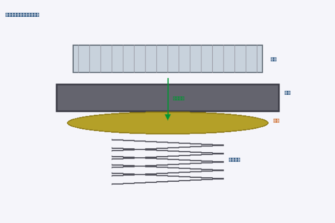
Figure 2: Schematic diagram of the base valve (compensation valve) structure in a shock absorber (including strainer/filter screen, valve seat, valve disc, and return spring)
Core Technical Points
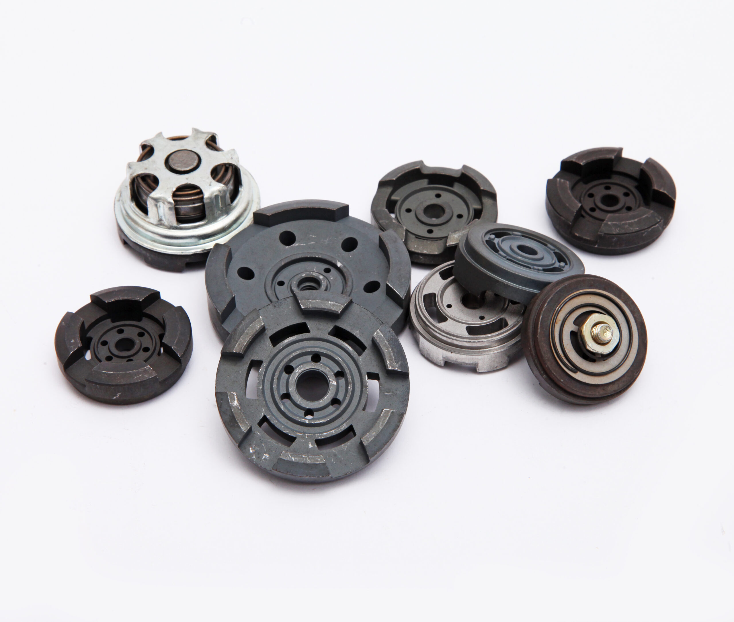
- In monotube shock absorbers, the base valve is responsible for volume compensation and works together with the floating piston to separate oil and gas.
- The valve opening pressure must be precisely matched to the gas chamber pressure — too high, and the valve locks up; too low, and the damping becomes mushy/loose.
- The high‑stiffness spring‑loaded poppet valve ensures stable flow under extreme impact conditions.
- Advantages: no foaming, extremely fast response, excellent heat dissipation, strong resistance to damping fade.
- Disadvantages: if the sealing ring fails, the entire unit must be scrapped; there is no multi‑stage buffer redundancy.
- The integrated hydraulic‑buffering throttling groove achieves dynamic synchronization between the base valve response and gas chamber expansion.
Detailed Content
In a monotube high‑pressure shock absorber, the function of the base valve is fundamentally different from that in a twin‑tube shock absorber.